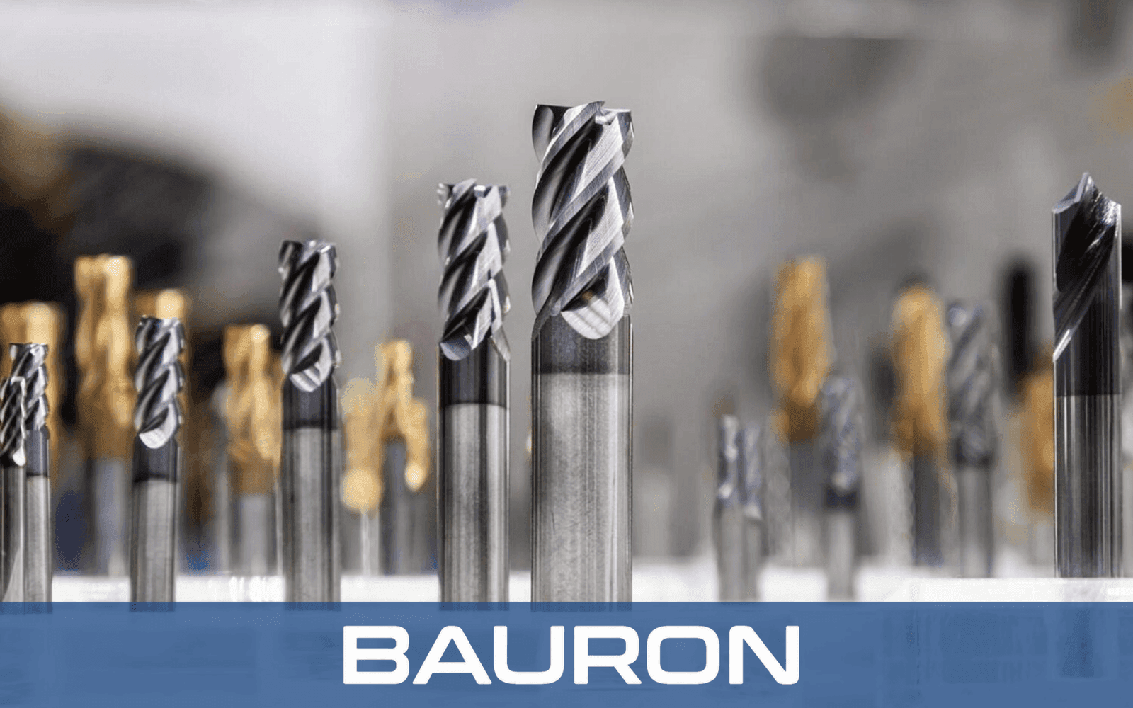
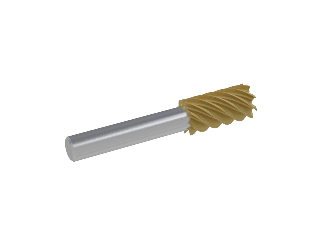
CNC end mills engineered with application-specific cutting geometry
CNC Milling Technical Guide

CNC End Mills Design Guide: Engineering Geometry for Maximum Performance

This technical guide details the core principles of end mill design, flute geometry selection, and custom tool engineering for high-performance CNC milling tools.

Explore the Guide Discuss Your Application
Technical overview

Principles of Engineering High-Performance Milling Tools

Optimizing end mill design is critical to stable chip evacuation, superior surface finishes, and maximum tool longevity across diverse workpiece materials. Modern CNC milling tools must balance cutting-edge strength with chip-clearing space, core rigidity, and heat management. Understanding how geometry variables interact allows engineers and machinists to select or design end mills for specific machining setups.

Core geometry

Fundamental Parameters in End Mill Design

Helix Angle

Higher helix angles of 45ยฐ to 60ยฐ deliver smooth, shearing cuts and high surface finishes on ductile metals such as aluminum. Standard 30ยฐ to 35ยฐ helix angles maximize edge strength for steel and cast iron milling.

Flute Count & Core Diameter

Two- and three-flute tools provide large chip gullets for soft materials. Four-flute to multi-flute designs increase tool-core rigidity and feed rates when profiling hard alloys.

Rake Angle & Relief Lands

Positive rake angles lower cutting forces and heat generation. Primary and secondary relief lands protect the cutting lip against friction wear and deflection.

Corner Profiles

Square, radius, and ball-nose profiles serve different operations. Corner radii strengthen the vulnerable cutter tip against chipping, while ball-nose profiles enable 3D organic contouring.

Dynamic stability

Advanced Geometry Engineering for Chatter Resistance

Harmonic vibration and chatter degrade part surface quality and cutting edges. Modern milling-tool design uses geometric features that disrupt harmonic frequencies during high-speed cuts.

Variable Pitch Flute Spacing

Unequal index spacing between flutes breaks repetitive cutting impacts and suppresses harmonic chatter.

Variable Helix Angles

Changing the helix angle along the flute length disrupts resonant-frequency feedback, allowing deeper axial depths of cut.

Differential Core Tapers

Tapering the internal core diameter toward the shank increases dynamic tool rigidity without sacrificing chip capacity at the tip.

Workpiece materials

Tailoring Milling Tool Geometries to Workpiece Substrates

Aluminum & Non-Ferrous Alloys

Use ultra-sharp edges, high positive rake angles, and two to three mirror-polished open flutes to prevent chip packing and edge welding.

Titanium & Nickel Superalloys

Variable-pitch four- to five-flute end mills with high radial clearance lands and heat-resistant PVD coatings withstand extreme cutting heat.

Hardened Steels Above 50 HRC

Thick core diameters, negative or neutral rake preparation, and micro-honed cutting lips absorb severe impact shock.

Composites & CFRP

Specialized compression flutes or burr-style diamond knurl patterns shear abrasive fibers cleanly without layer delamination.

Mill types

CNC Milling Tools by Category

Bauron manufactures the full spectrum of milling geometries, grouped by application. Each category diagram below is paired with the specific mill types it contains.
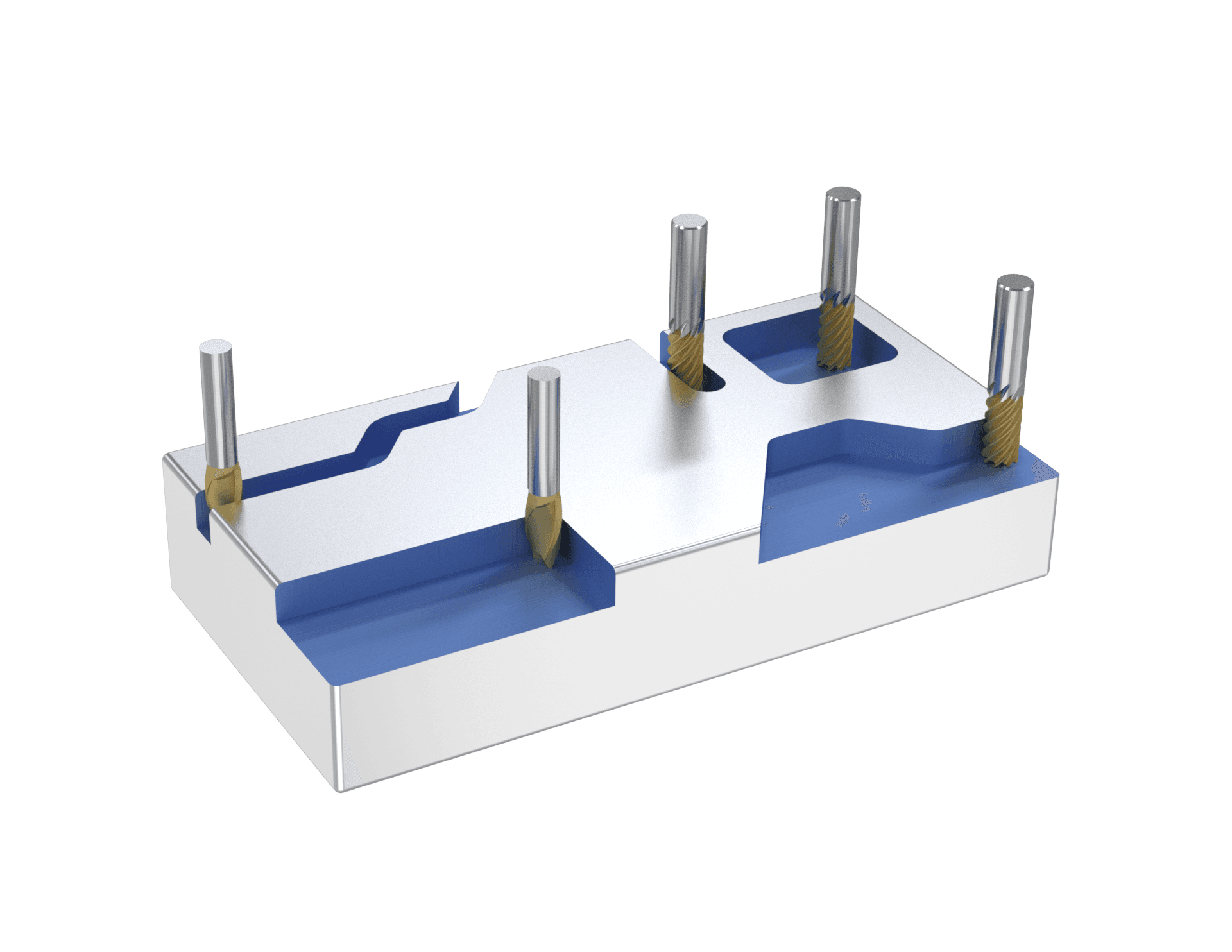
General-purpose CNC end mills

A. General-Purpose Mills

Standard cutters for everyday milling, cutting, and shaping.
  • End Mills โ€” standard tool for everyday milling, cutting, and shaping
  • End Mill Neck Relieved โ€” reduced neck for deep cuts around obstructions
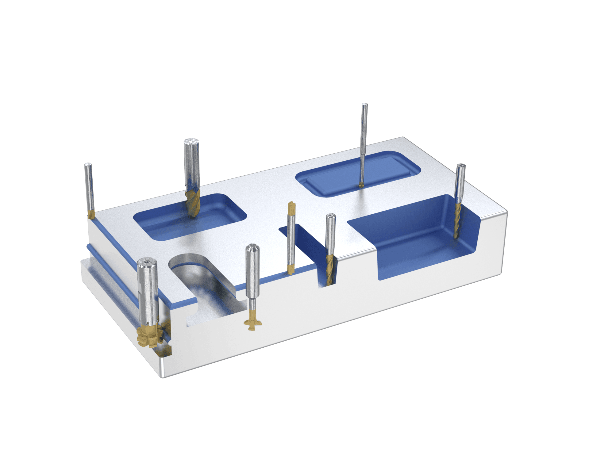
Profiling and contouring end mills

B. Profiling & Contouring Mills

Radius and taper geometries for sculpting 3D surfaces and profiles.
  • Concave Radius Milling Cutter โ€” shapes concave radii and profiles
  • Back Corner Rounding End Mills โ€” rounds edges on the reverse side of a part
  • Corner Rounding End Mill โ€“ Double End โ€” rounds edges with both ends
  • Corner Rounding End Mill โ€“ Single End โ€” rounds edges with one cutting end
  • Tapered End Mill โ€” angled surfaces and precise mold features
  • Tapered Ball Nose End Mill โ€” taper + ball nose for intricate detail
  • Lollipop Cutters โ€” undercuts and complex 3D geometries
  • Ball Nose End Mill โ€” rounded tip for 3D surfaces and contours
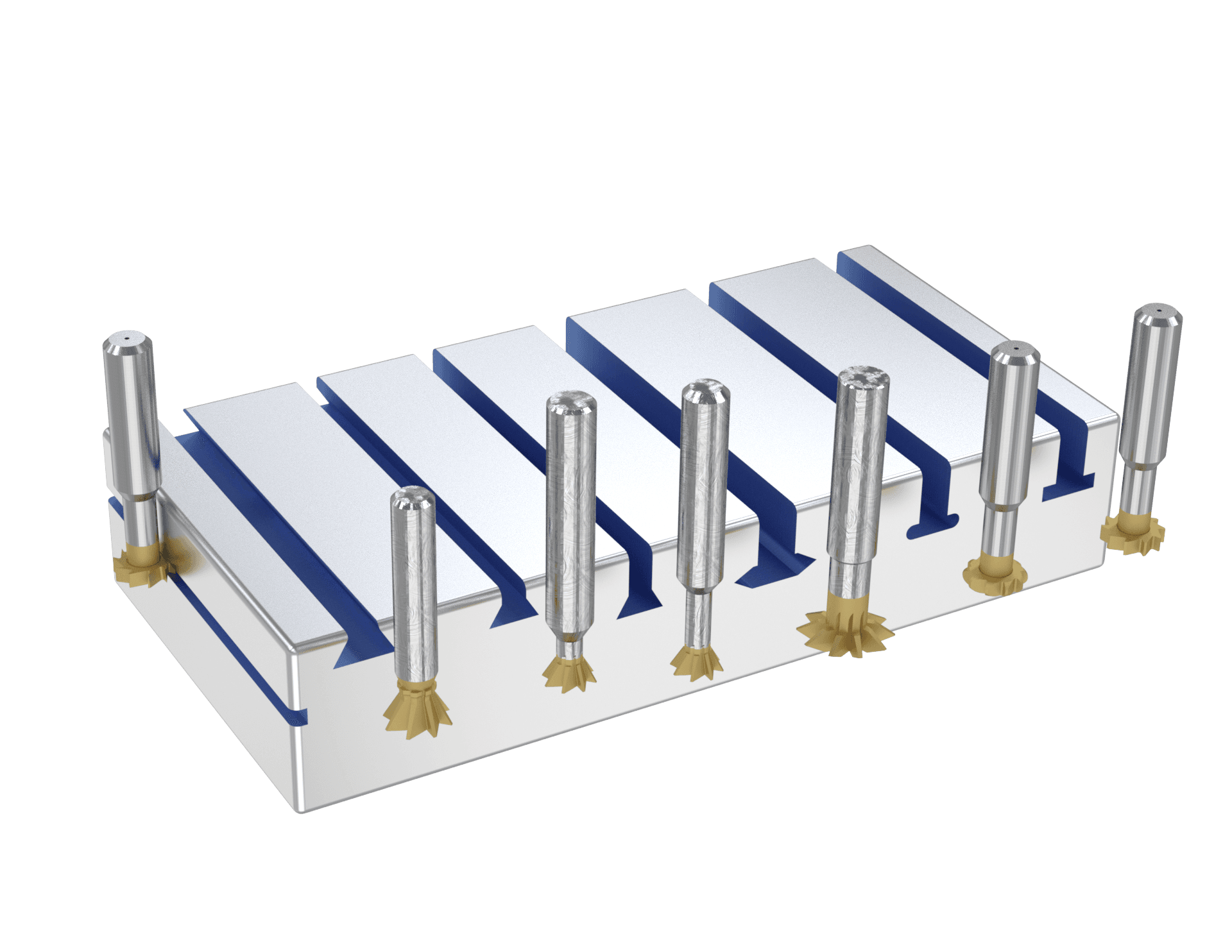
Slotting and grooving end mills

C. Slotting & Grooving Mills

Dovetail, angle, and keyseat cutters for slots and grooves.
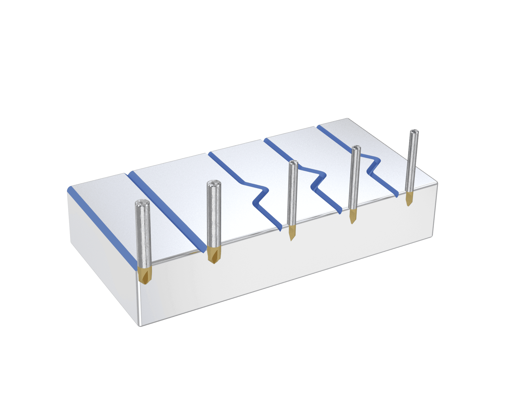
  • Dovetail Cutter โ€“ with Neck Radius โ€” reduces stress during dovetail cutting
  • Dovetail Cutter โ€” machines dovetail slots for assembly components
  • Dovetail Cutter โ€“ with Long Reach โ€” deeper, harder-to-access dovetails
  • Double Angle Shank Cutters โ€” V-shaped grooves and angular cuts
  • Keyseat Cutter โ€“ Full Radius โ€” rounded keyways for special applications
  • Keyseat Cutter โ€” cuts keyways in shafts for keyed assembly
  • Keyseat Cutter โ€“ Staggered Tooth โ€” reduces vibration and chatter
Chamfering and engraving end mills

D. Chamfering & Engraving Mills

Pointed and radiused tips for beveling, engraving, and fine detail.
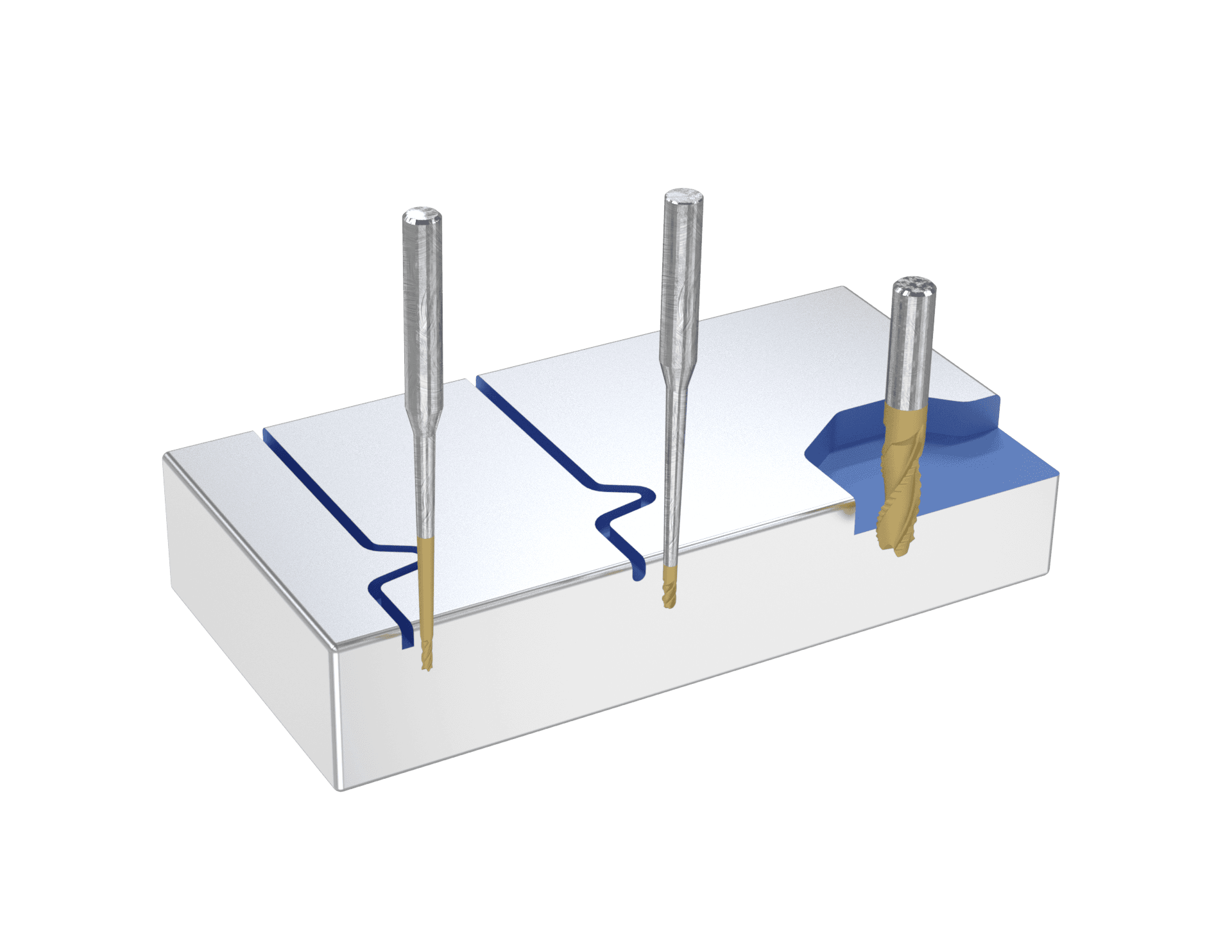
  • Chamfer Cutters โ€“ Pointed โ€” beveled edges for finishing and assembly
  • Engraving Cutter โ€“ Tipped Off โ€” precision tip for intricate engraving
  • Engraving Cutters โ€“ Pointed โ€” sharp point for detailed markings
  • Radius Engraving Cutters โ€” radiused tip for smooth, curved marks
  • Tipped-Off Chamfer Cutters โ€” precise, consistent beveling
Clearance and finishing end mills

E. Clearance & Finishing Mills

Extra-clearance and chip-control geometries for finishing passes.
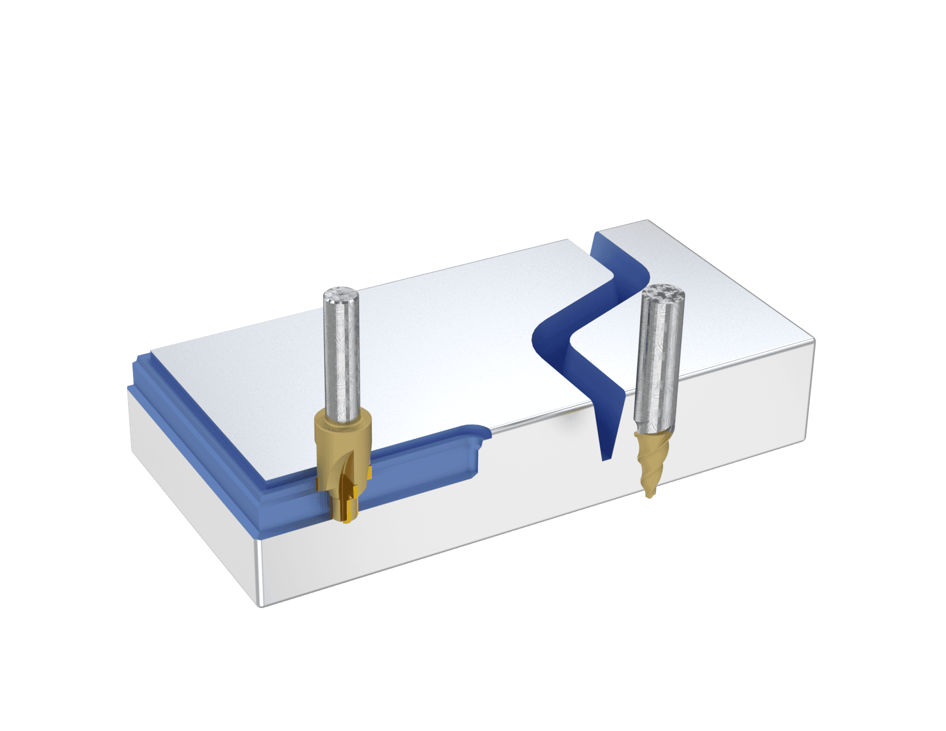
  • Clearance Cutters โ€“ Square End Mill โ€” flat end with added clearance
  • Clearance Cutters โ€“ Ball End Mill โ€” extra clearance for tight machining
  • Chipbreaker End Mill โ€” serrated edge reduces chip size
Die-sinking and specialty end mills

F. Die-Sinking & Specialty Mills

Precision tools for cavities, dies, molds, and internal passages.

  • Die Sinking Cutters โ€” detailed cavities in dies and molds
  • Porting Tools โ€” enlarge and refine internal passages
Shank options

Shank & Tool-Style Options

Every Bauron end mill can be produced with the shank interface that best matches your machine and holder. Each shank type below is shown with how it mounts and where it performs best.
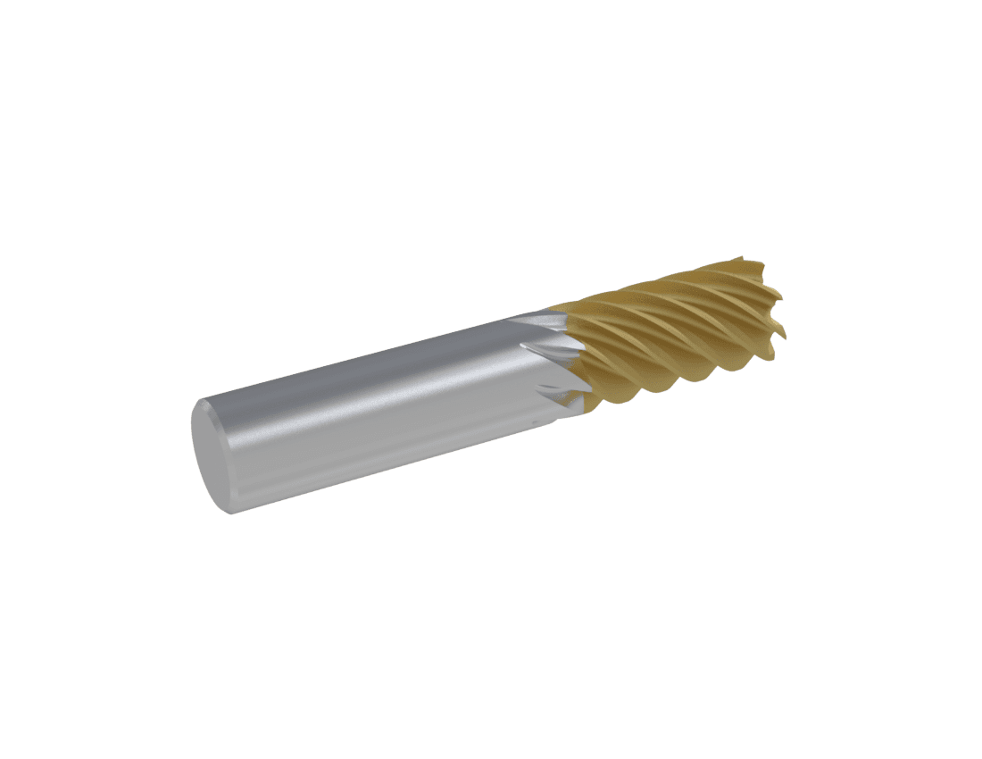
Straight Shank end mill

Straight Shank

  • Profile: uniform cylindrical shape
  • Held: clamped into a collet chuck or drill chuck
  • Best for: general-purpose tools like drills and end mills
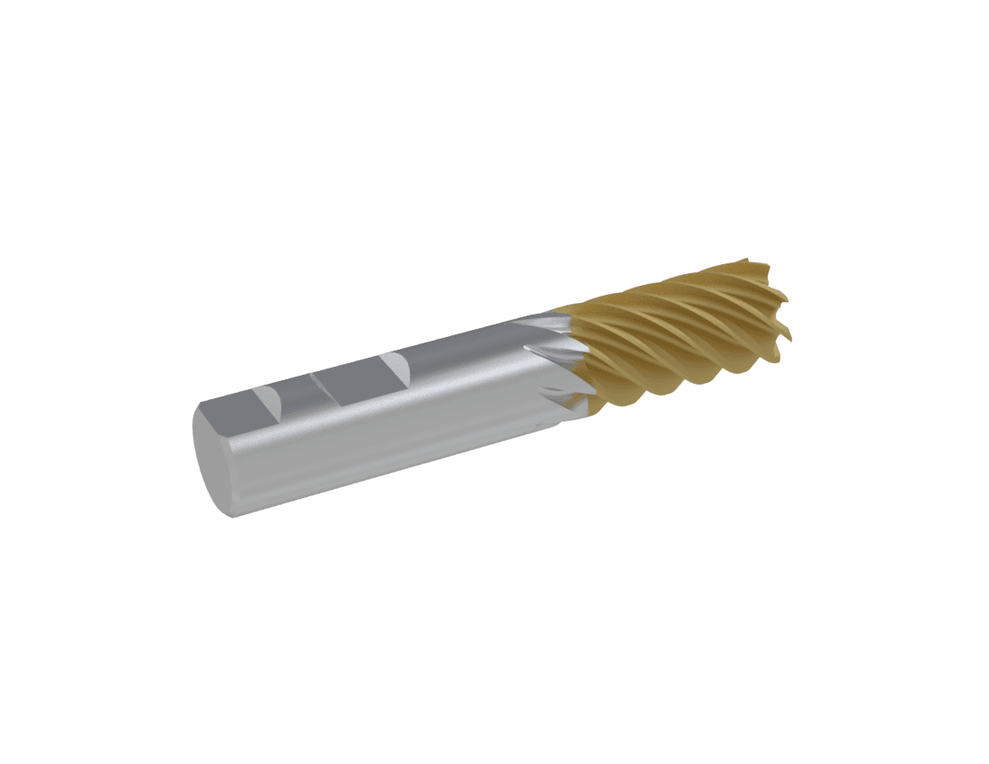
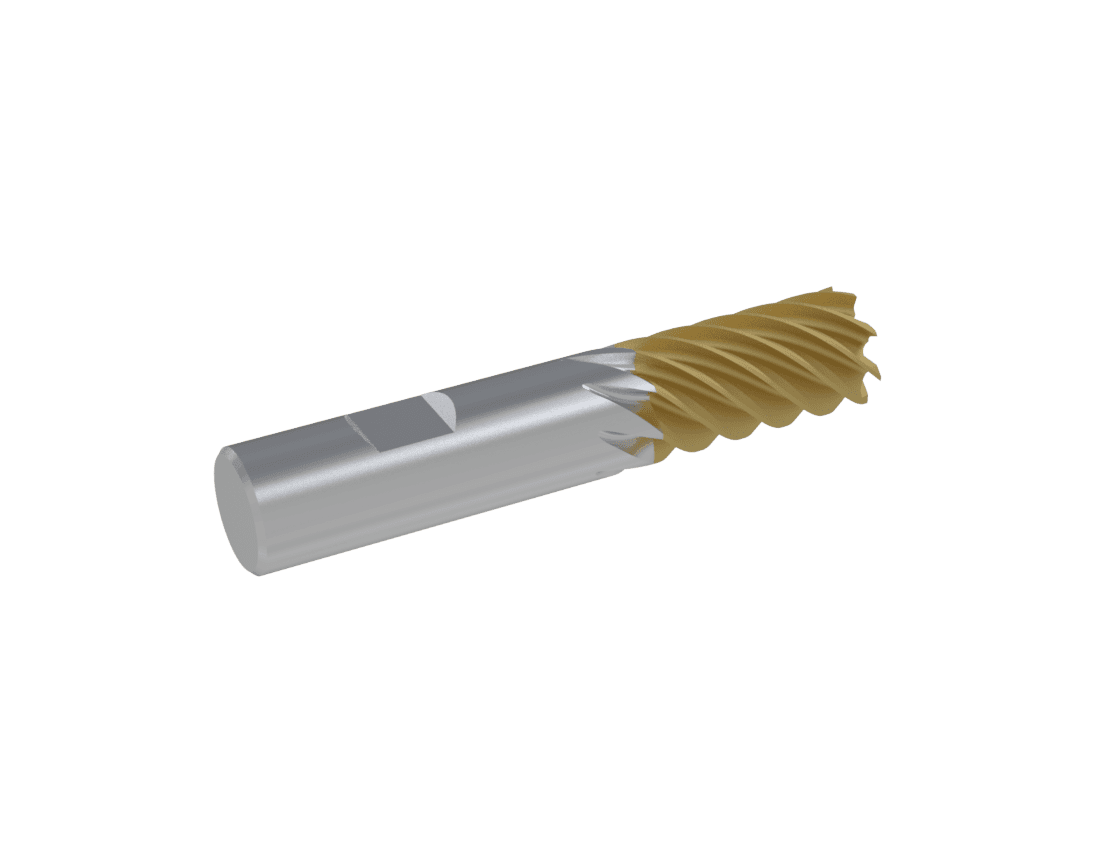
Weldon Shank end mill

Weldon Shank

  • Profile: cylindrical with one flat machined into the shank
  • Held: set screws in a side-lock tool holder
  • Best for: tools requiring high torque and secure gripping
Double Weldon Shank end mill

Double Weldon Shank

  • Profile: like a Weldon shank but with two flat sections
  • Held: improved grip in side-lock holders
  • Best for: high-precision or high-torque operations
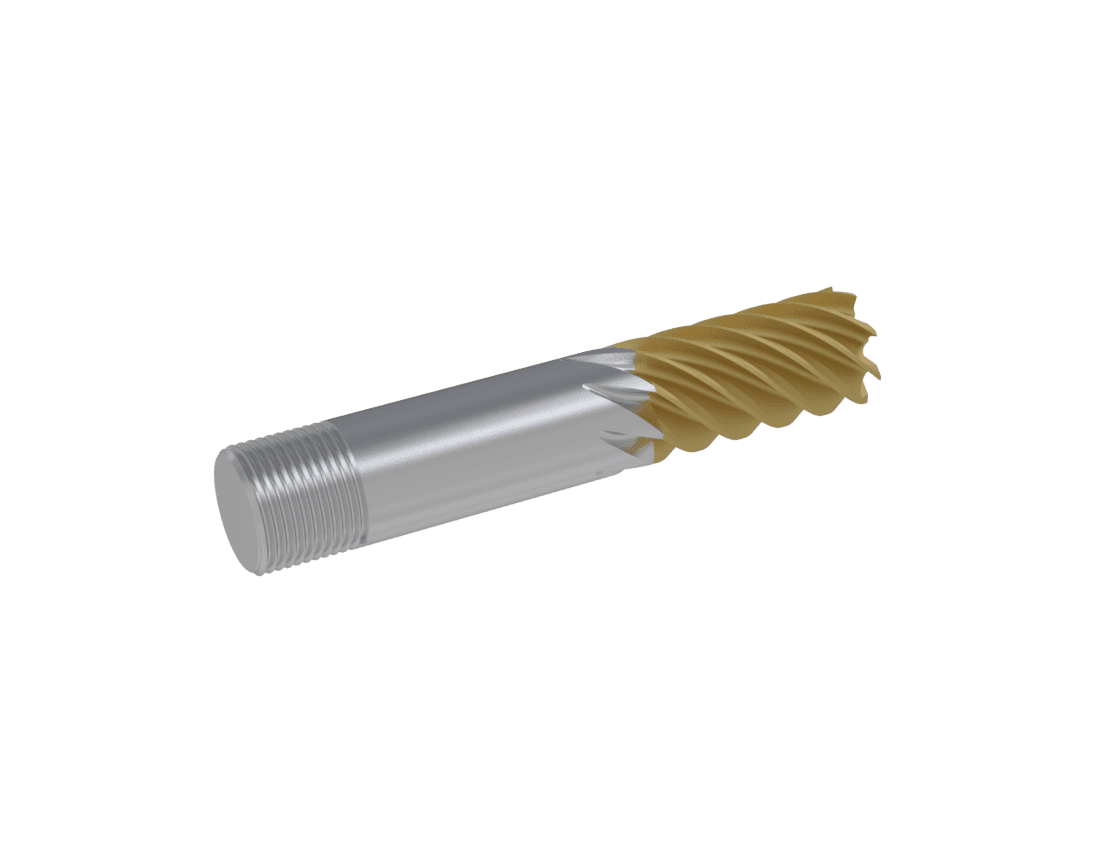
Threaded Shank end mill

Threaded Shank

  • Profile: cylindrical shank with threads at the end
  • Held: screwed into tool holders or extensions
  • Best for: tapping and reaming applications
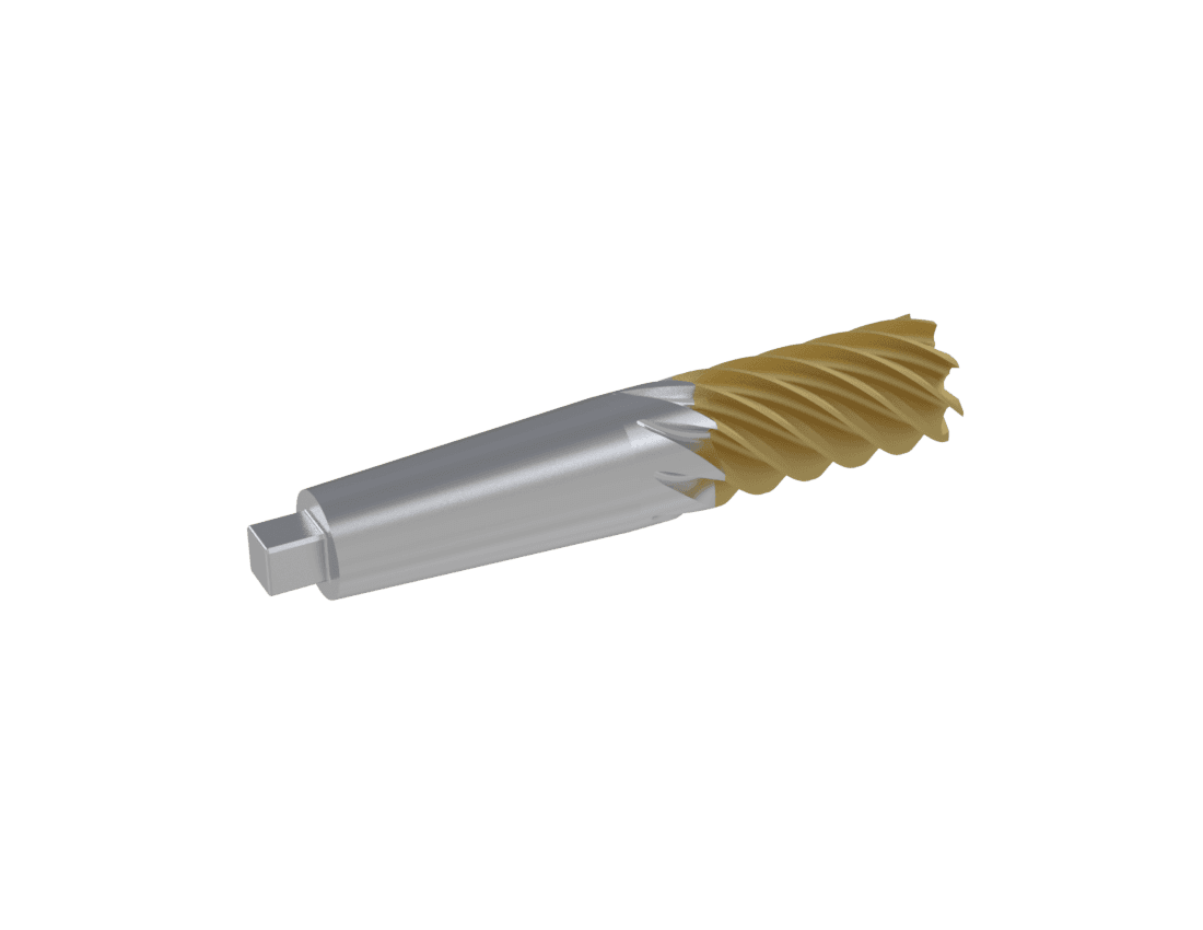
Tapered Shank end mill

Tapered Shank

  • Profile: conical / tapered (e.g. Morse taper)
  • Held: fits into matching taper sleeves or spindles
  • Best for: machines with taper sockets
Reduced Shank end mill

Reduced Shank

  • Profile: shank diameter smaller than the cutting diameter
  • Held: standard collets or chucks
  • Best for: when tool diameter exceeds chuck capacity
Technical questions

Frequently Asked Questions

How does helix angle selection affect CNC milling-tool performance?

A higher helix angle creates a smoother shearing action and pulls chips upward from deep cavities, making it suitable for non-ferrous materials. Lower helix angles provide greater tooth strength and resist axial lifting forces, which benefits tough-steel profiling.

Why is core diameter important in end mill design?

Core diameter dictates structural rigidity. A larger core increases beam strength and helps prevent deflection and chatter during heavy cuts, but reduces the flute-gullet space available for chip evacuation.

Can Bauron manufacture custom CNC milling tools from specific blueprints?

Yes. Bauron engineers bespoke flute geometries, variable-pitch flutes, custom corner radii, and specialized neck clearances directly from CAD drawings.

What role do PVD coatings play in end mill design?

Advanced PVD coatings such as AlTiN, DLC, or nACo act as thermal and friction barriers. They allow tools to run at higher surface feet per minute while preserving the sharp ground geometry beneath the coating.

Application support

Collaborate with Bauron on Custom Milling Tool Design

Need optimized end mill geometries, custom profiles, or specialized high-feed cutters for your machining line? Consult with a Bauron application engineer.

Request a Design Quote Contact Bauron
Design and engineering support

From application details to a production-ready tool.

Bauron works with manufacturers to review tool geometry, substrate, coating, reach, machine conditions, and production requirements for standard and custom CNC tooling.

Submit your requirements
Get a QuoteDesign Tool